Videos – Economy Cycle Mode & Return Air Bypass Mode
Confused by Economy Cycle Mode or Return Air Bypass Mode for ERV / HRV units? Then watch these vi...
May 2021
Stay up to Date
Confused by Economy Cycle Mode or Return Air Bypass Mode for ERV / HRV units? Then watch these vi...
May 2021
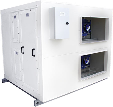
Plantroom or Rooftop Mounted Energy Recovery Ventilators
Home

Once upon a time, air conditioner thermostats were simple mechanical devices that relied upon principles like the deflection of temperature sensitive metal in order to signal when a unit needs to switch on and off. Not only are air conditioner thermostats now electronic and programmable, but the use of variable capacity inverter compressors in an increasing number of packaged air conditioners and other types of equipment is demanding additional complexity of thermostat control systems. This is because reliable control algorithms that are more complicated than traditional on/off logic are essential for modulating the output of these modern air conditioning units accurately and stably with respect to a heating or cooling load.
Recognising the importance of proper thermostat control is paramount, as the benefits of the latest and greatest air conditioning hardware (like improved temperature control precision and energy efficiency for example) can be negated without adequate “brainpower” driving it. Improper control can even be detrimental to variable capacity equipment, with haphazardly controlled compressor speeds or on/off cycling leading to increased wear. This article will therefore cover the basics of common thermostat control methodologies, along with an overview of the Air Change control approach which is included with the ClimaSync Control System.
The focus of this article is on variable capacity control methodologies, however for background knowledge it will be beneficial to cover how traditional fixed capacity thermostat systems work.
Fixed capacity systems require a temperature hysteresis (also commonly referred to as a deadband) to accompany the setpoint temperature. This hysteresis is a window where in which the on/off control state of the air conditioner compressor does not change and allows the room temperature to be maintained within an acceptable tolerance.
For example, the below cooling scenario in figure 1 shows a compressor operating until the room temperature meets the lower hysteresis limit of 23°C. The compressor then switches off until the room warms to the upper hysteresis limit of 25°C where the compressor switches back on again, and the cycle continues for as long as the space requires cooling. This results in an average room temperature that is equal to the required setpoint temperature of 24°C, however the inherent temperature fluctuation may not be acceptable for mission critical applications.
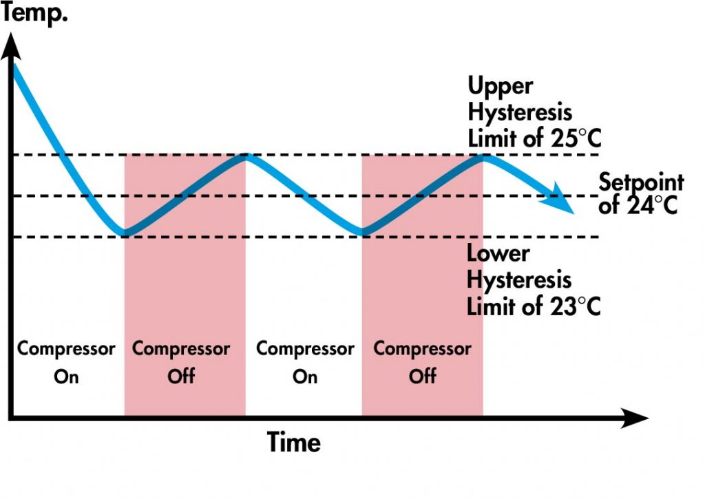
Figure 1: Fixed capacity temperature control.
PID controls are the most conventional and widely used algorithms for not only variable capacity thermostats, but also other machine processes in general that require modulating control. They are feedback loops that continuously calculate the error between a desired setpoint and the current measured condition, and then use well-known mathematical principles that deal with continuous change to generate a control output that is suitable for correcting the error.
The below schematic demonstrates the basic operating principle of a PID loop used in a variable capacity thermostat application, where the PID controller continuously calculates the control output (eg. variable 0-10V compressor speed signal) required to maintain the air temperature at the setpoint.
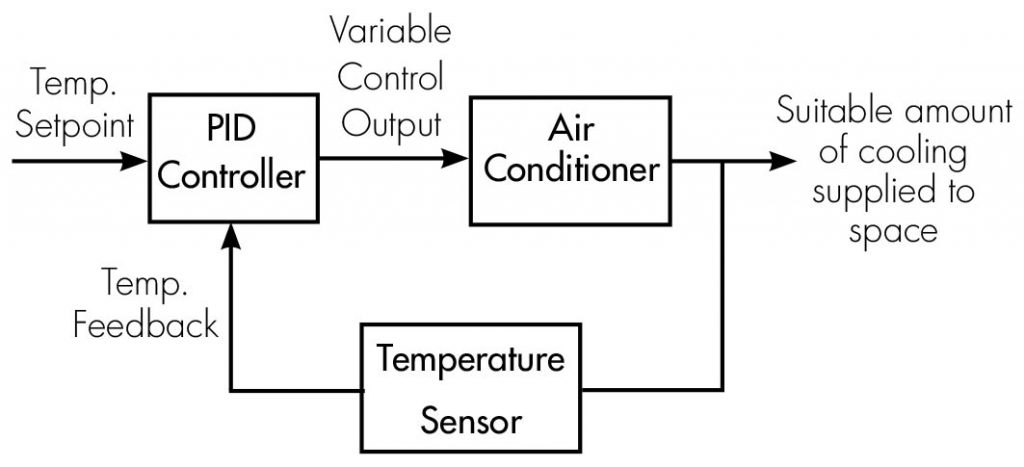
Figure 2: PID loop schematic for variable capacity air conditioner control.
The name PID stands for Proportional, Integral, and Derivative which refer to the three types of mathematics that govern the control output. For those of you who want to dust off your old calculus textbooks, the mathematical function of control output u(t) with respect to the measured error e(t) is expressed below (there are often variations in representation, but the underlying principle remains the same).
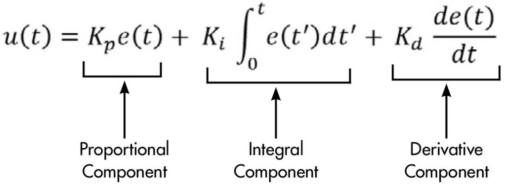
Figure 3: PID mathematical equation.
The role of each of the PID components is as follows.
Proportional- The proportional component of PID draws upon the present to influence the control output proportionally to the error. Its effects are most relevant when the error between the setpoint and measured condition is large.
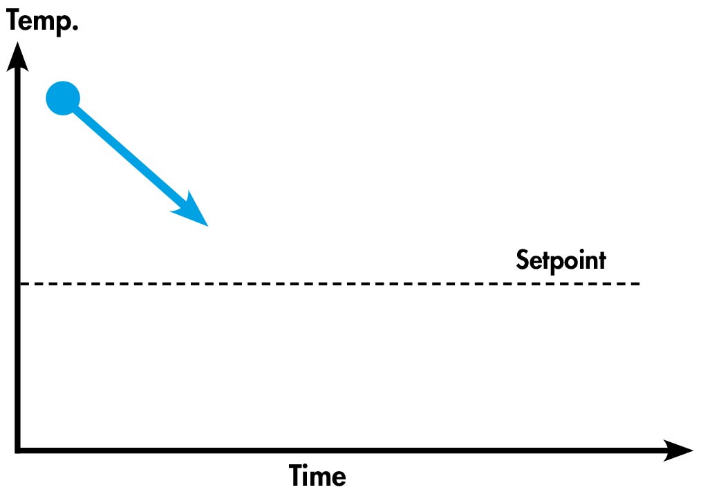
Figure 4: Effect of proportional component in PID control.
Integral- The integral component of PID uses integral calculus to draw upon the past and its influence on the control output helps the measured condition meet the setpoint in a stable manner.
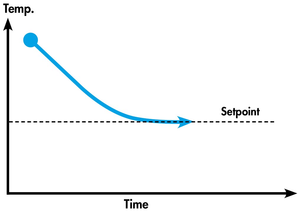
Figure 5: Effect of integral component in PID control.
Derivative- The derivative component of PID uses derivative calculus to forecast into the future and its influence on the control output helps minimise overshoot of the setpoint which improves stability.
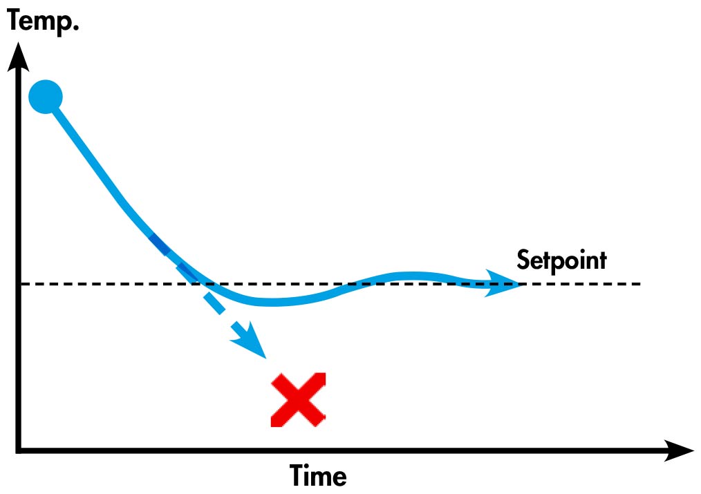
Figure 6: Effect of derivative component in PID control.
Each of the PID components include a coefficient (Kp, Ki & Kd) which need to be tuned to a particular application for optimal performance. A well-tuned system will have a fast settling time along with little to no temperature oscillation around the setpoint. However, the dynamic loading and non-linear control nature (meaning that control outputs aren’t proportional to the actual resulting process effect) of HVAC systems makes achieving optimal PID tuning difficult and performance can vary. Despite this, PID controls are widely used in HVAC equipment because they are relatively simple to implement.
Fuzzy logic is another common thermostat control methodology for variable capacity air conditioners that could be considered to be less purely calculative and more heuristic than PID control. It is a concept that is probably easiest explained through an example:
Step 1: Fuzzification
The initial step involves taking “crisp” control inputs and then “fuzzifying” them by mapping them onto a pre-constructed fuzzy set which consists of membership functions. For example, a measured room condition of 30°C is classified as mostly “Scorching” where the degree of membership is 0.5, and a bit “Hot” where the degree of membership is 0.25.
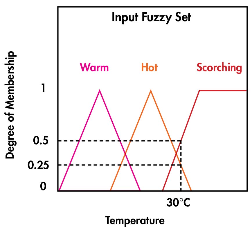
Figure 7: Control input fuzzy set.
Step 2: Fuzzy Inference
The next step involves using predetermined rules that govern what the required “fuzzy” response needs to be. The rules that would likely apply to a scenario like this would be:
-If room temperature is scorching, then compressor speed needs to be fast.
-If room temperature is hot, then compressor speed needs to be medium.
-If room temperature is warm, then compressor speeds needs to be slow.
In this case, as the room temperature is determined to be mostly “Scorching” and a bit “Hot”, the system response needs to be a mixture of “compressor speed needs to be fast” and “compressor speed needs to be medium”.
Once the appropriate fuzzy outputs are determined through the inference rules, the degree of membership for the control inputs can be mapped onto a separate fuzzy set for the corresponding control outputs.
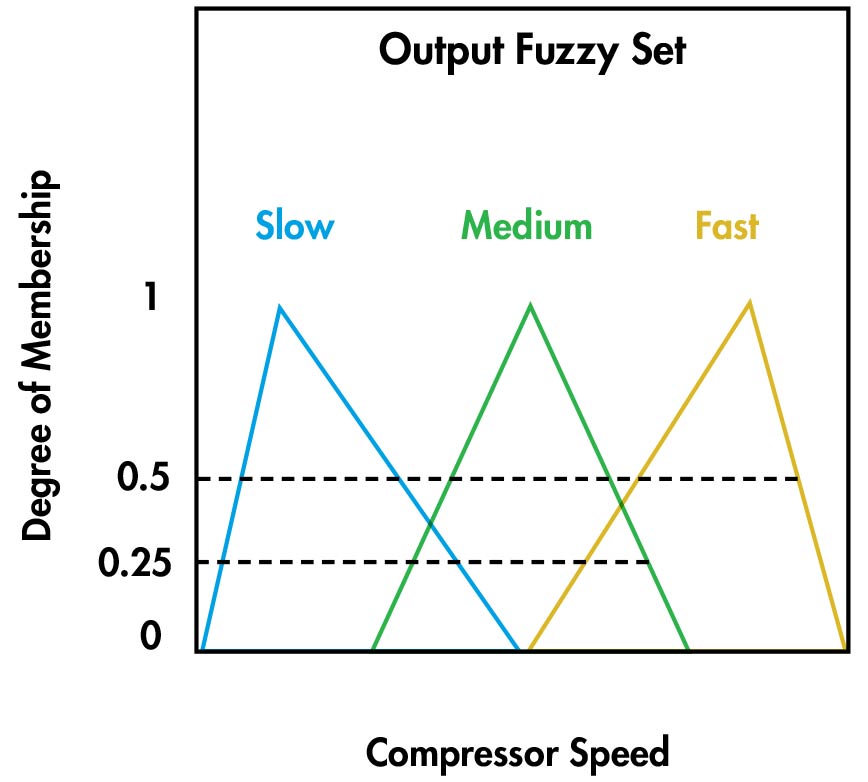
Figure 8: Control output fuzzy set.
Step 3: Defuzzification
The defuzzification step involves converting the “fuzzy” output into a “crisp” output that the air conditioner can use (eg. compressor revolutions per second). There are numerous methods of achieving this, however the centroid approach is a popular one. In this case, the centroid of the active portions of the Medium and Fast membership functions equates to a compressor speed of 85 RPS.
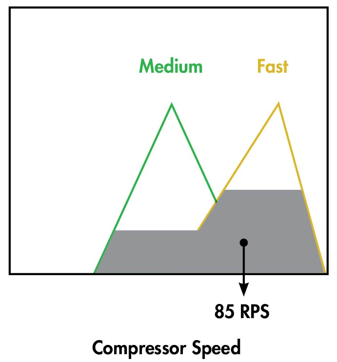
Figure 9: Defuzzification by centroid method.
Fuzzy logic is a design-flexible approach with numerous factors like the number of fuzzy sets (for multiple control inputs/outputs), the shape of membership functions, the inference rules, and the defuzzification method all contributing to the behaviour of the system and how well it performs. Well-developed fuzzy controls can be designed around the dynamic and non-linear control nature of HVAC systems which results in very good performance, but they can also consequently become quite complex. Development of fuzzy controls also requires high prescriptive knowledge of how a system should behave in certain scenarios, which could possibly lead to uncertainty of performance in untried situations.
At Air Change, we have invested extensive R&D into thermostat control methodologies, and have developed our Proactive Thermostat Logic which is included in the ClimaSync Control System. By building on top of basic thermostat control theory, we have created a control model that is both accurate and stable, while also being versatile enough to be easily applied to a wide range of projects varying in demand and dynamics.
Figure 10 below is a realtime screenshot from one of our Precise Control Units currently in operation. The Proactive Thermostat Logic precisely modulates the compressor speed and associated components to ensure the measured air condition consistently sticks to the setpoint. By being able to better perceive a required load, it is able to soften non-linearities of the system which improves control stability. Additionally, by being less reactive and more proactive in nature, compressor off-cycling is kept to a bare minimum which improves temperature control precision and compressor longevity. Further, the advanced control techniques applied minimise the need for project specific tuning, but if it is required, our engineers are able to login remotely for any necessary adjustments.
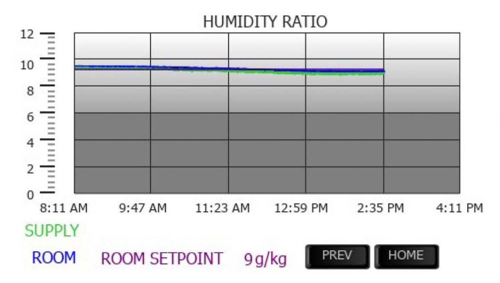
Figure 10: Compressor running proactively to keep the room condition at the required setpoint.
Not only can the ClimaSync Control System manage temperature, but it can also precisely and synchronously regulate humidity and airflow. Figure 11 below is a trend-line screenshot, demonstrating close control of room humidity over several hours through the modulated control of supply air cooling and reheat. This ability to accurately control humidity alongside temperature caters for a wide range of Sensible Heat Ratios. With regards to airflow, the integrated control of fan speed simplifies unit commissioning and ensures ongoing performance by maintaining a required airflow setpoint (despite any pressure changes in the system) or a required duct pressure setpoint for VAV installations.
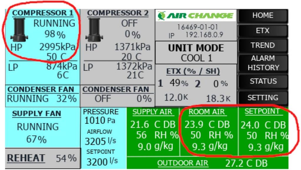
Figure 11: Humidity ratio trendline (the room setpoint line is hidden behind the room measured condition line).
As Air Change Dehumidification units are highly customisable, the ClimaSync Control System needs to be equally so. Because of this, not only can the control logic be tailored to meet project specific requirements, but also other aspects like user interface and connectivity. Additionally, our ability to remotely monitor unit performance via the internet allows us to quickly troubleshoot issues or even help prevent them from occurring in the first place.
At Air Change, we have a big appreciation for the control aspect of air conditioners and we are really excited about the future of this space. This is why we are ambitiously continuing our research in broader aspects of thermostat and air conditioner control in an effort of making further advancements in air conditioner performance, usability, and energy efficiency. Stay tuned!
This article was written by Matthew Gellert who is a Business Development Engineer at Air Change.
We will happily meet with you to discuss your project and our products at a time that suits you.
© Copyright 2020 Air Change Australia. Air Change products internationally patented protected. Refrigerant Trading Authorisation No. AU23586 | Privacy Policy | Terms and Conditions of Sale | Warranty Policy | Site by AAM